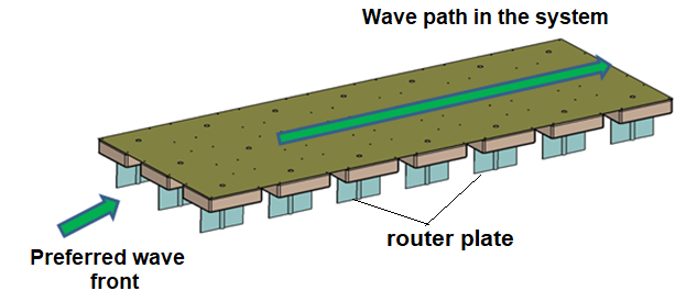
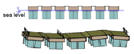
1 – The direction of the wave to the system is not important and it is directed under the flexible surface by means of wave buoys.
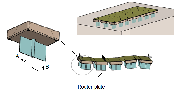
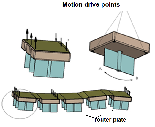
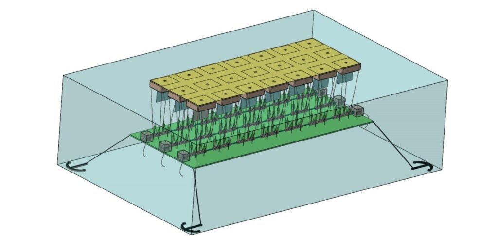
2 – The routers connected to each float are able to rotate in their own axes (in A-B directions) with respect to the direction of the wave and with the effect of the wave, thus forming channels along the whole flexible surface and allowing the wave to travel under the flexible surface as much as possible.
3 – The system is designed to contain a certain depth according to the wave façade. We create a controlled resistant surface through the flexible surface, providing a controlled power transfer across the flexible surface depth. This approach contributes to cycle efficiency
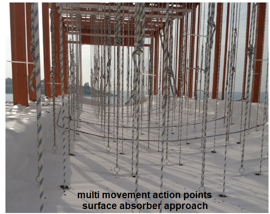
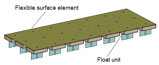
4 – The movements formed on the flexible surface of the wave formed under the flexible surface along the channels formed by the routers are attempted to be captured at many points, the movements on almost all the flexible surface are directed directly by the multipoint / surface absorber approach to activate the power shaft. Here, the flexible surface waves serve as an interface where we can touch. Wave effect at any point on the flexible surface activates points close to this point and captured by the multipoint absorber approach which significantly improves cycle efficiency.
5 – With the flexible surface, the sensitivity of capturing the sea surface movements and transferring them to the energy production cycle is very high and the system can operate at high efficiency with low wave heights.
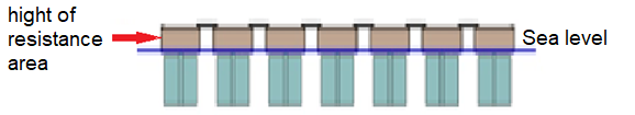
6 – The fact that the flexible surface positioned on the sea surface does not create a destructive resistance surface against the wave provides unpredictable wave heights (in cases where it cannot be guided under the flexible surface), leaving the system over the flexible surface and preventing the damage of the system.
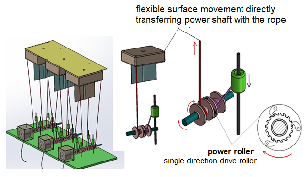
7 – The drive links, which reflect the wave effects on the flexible surface, directly activate the power shaft. This minimizes losses in direct drive power transmission mechanisms and increases efficiency.
8 – Cycle system design allows for both nearshore and offshore applications.
9 – The cost of the units forming the cycle system is low and the system can be manufactured as modules. Modular manufacturing provides transportation and installation convenience, contributes to the regular operation of the system and reduces maintenance-attitude costs.
SUMMARY :
1- The waves are directed under the flexible surface, the direction of the wave is not important.
2- The channel is created by means of the routers under the flexible surface. Allows waves to travel under the flexible surface
3- The movements created by the wave on the flexible surface are transferred to the power shaft from many points connected to the flexible surface. Energy loss is minimized.
4- The depth of the flexible surface creates time to transfer the wave effects to the power shaft. Controlled power transfer is provided, efficiency increases.
5- Since the wave effects on the flexible surface are transmitted directly to the power shaft and alternator, the losses are very low.
6- Unexpected wave heights pass over the flexible surface in the system and do not damage the system. Our system does not create a direct resistance surface against the wave.
7- There is no system element that will create visual pollution on the sea surface. It has an aesthetic appearance
8- The system can be produced as modular. Ease of transportation and installation and cheaper