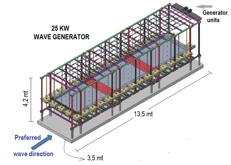
25 KW Waveform generator design
In this first wave generator application, the main carrier-foundation structure is preferred. The aim was to make the interventions on the system easier and to make better observations. In our next application (as described below) the lattice system will be freed and the machine is lowered into the sea and there is no structure on the sea level. Thus, the system has a very aesthetic structure, has been freed from the visual pollution and at the same time, it has become compatible with the open sea application.
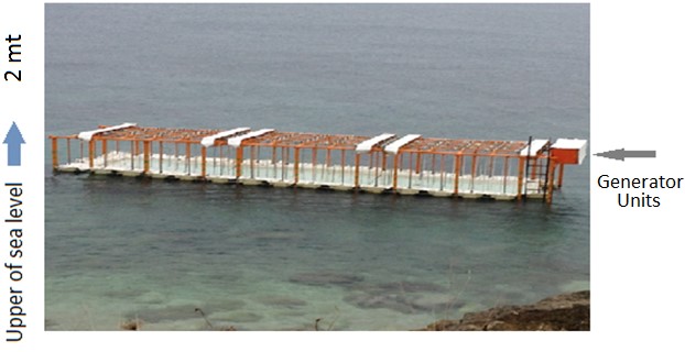
25 KW Waveform generator field installation
System installed capacity (7 – 8 kw / mt): 25 KW
System production capacity (with 40% efficiency): 10 KWH
Year average productions (with 70% utilization rate): 85 MWH
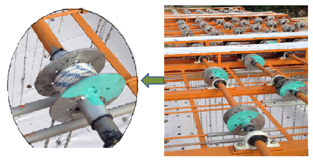
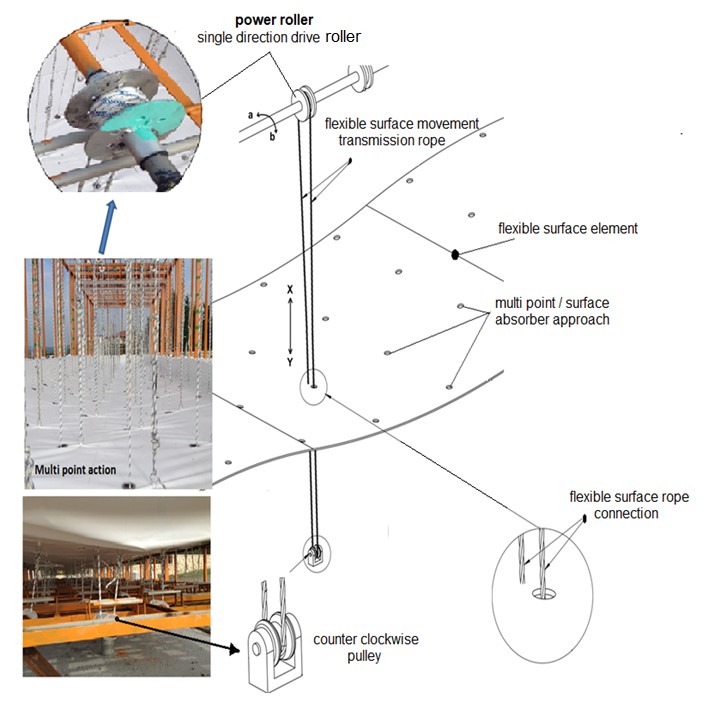
In the figure, the unidirectional pulleys are shown which are driven by the ropes connected to the flexible surface. By pulling the drive point from many nudes on the flexible surface, by connecting the ropes to these drive points (there are 86 drive points in our system), most of the movements with the wave effect on the flexible surface are transferred directly to the unidirectional pulley and hence to the power shaft through these ropes. The unidirectional rollers enable the flexible surface to rotate in an active manner to produce the shaft in the upward motion with the effect of the wave, and in the downward direction of the flexible surface, it becomes ready for the next movement by turning in the opposite direction with the flexible surface without creating resistance.
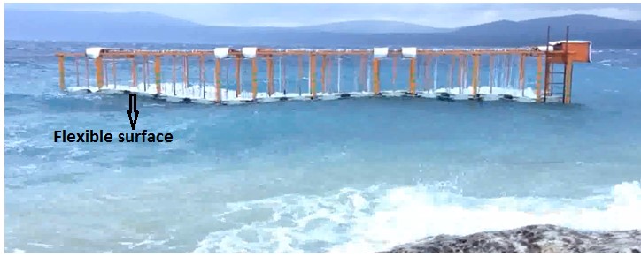
25 KW Waveform generator field application
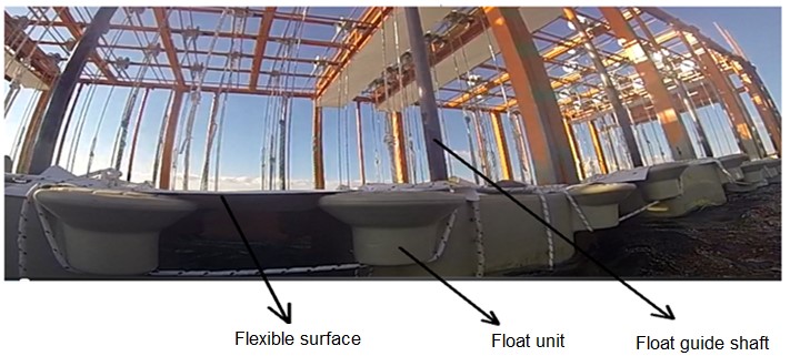
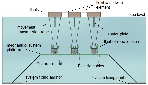
Flexible – Flexible surface edges are connected to the buoys from the top as seen in the application, so that the incoming waves can be directed under the flexible surface. The buoys move on their own guide shafts with an up-down wave effect while keeping the flexible surface edges attached to them constantly above sea level and allowing the waves to go under the continuous flexible surface.
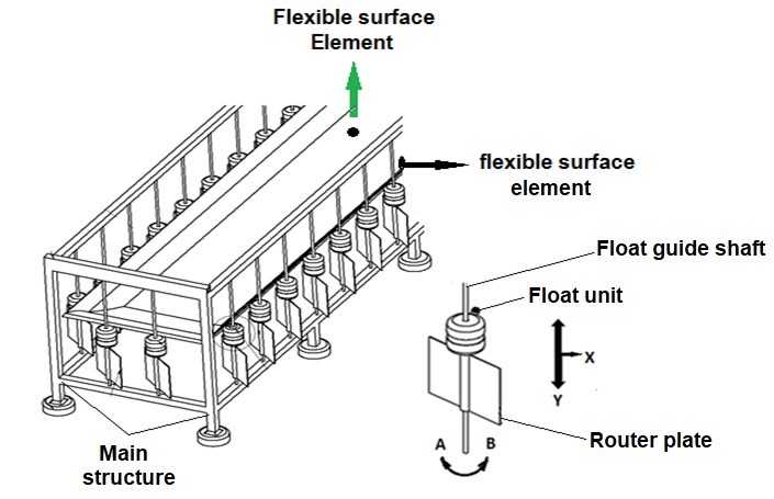
Flexible surface element / Flexible surface:
The edges of the flexible surface that will work by reflecting the wave movements are connected to the buoys. Thus, the buoys moving up and down along the y-axis with the effect of the wave, allow the incoming waves to enter under the flexible surface by keeping the flexible surface edges slightly above the sea surface. The direction of the arrival of the waves is not important;
Router:
The float is below the float that moves with the up-down wave effect on the guide shaft. According to the direction of the wave, A-B rotates around its axis and forms a channel under the flexible surface and allows the wave to move under the flexible surface as much as possible.
The flexible surface edges are held up by the floats at some level above sea level so that the incoming waves can be directed to the bottom of the flexible surface. The waves that are directed under the flexible surface are prevented as much as possible by avoiding the waves out of the system due to the fact that the direction of the wave coming to the system is not important, and the routers are rotating with the effect of the wave in their axis.

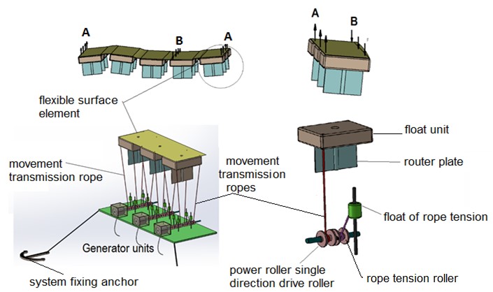
• The flexible surface element placed on the sea surface is attached to the buoys by its edges. The edges of the flexible surface element are kept slightly above sea level by means of floats. The upward and downward movements of the buoys by moving the upward and downward movement of the flexible surface element edges with its own movement, ensure that these flexible surface edges are constantly above the sea surface, which is the same as the direction of the waveguides.
• The flexible kinetic energy under the flexible surface is transferred directly to the power shaft by means of ropes connected to the flexible surface. it provides a more controlled power transmission by spreading the effects it creates on the flexible surface to a certain time.
• As can be seen from the figure above, the rope connected from the bottom to the flexible surface is guided from the reverse direction pulley and through the perforated portion on the flexible surface to the unidirectional drive roller and then to the flexible surface again from the top. The rope continues its movement in the direction of the y-axis in a closed loop frame in the direction of the y-axis, depending on the flexible surface
• The flexible surface moving upward in the y-axis with the effect of the wave, pulling the rope connected to it downwards in the direction of the y-axis with the effect of the reverse direction roller It rotates in the direction of a and starts the production of energy.
• In the period of the impact of the wave and the falling down of the flexible surface (the flexible surface falls down on the y-axis, the rope attached to it will rise upwards on the y-axis with the effect of the reverse direction roller and the unidirectional pulley of the power shaft turns idle in the direction of b, without any resistance to the power shaft. The flexible surface will move to a new position for a new effect with the return of the reverse direction pulley without any resistance in the direction of B.
• The number of power shafts with flexible surface movements in the system which translated by the transmitting ropes can be more than one (we have six units in our field prototype study.
• We have created a structure that will rotate all shafts with each movement on the flexible surface by making chain-threaded connections with each other in our system, the smallest movements on the flexible surface. we have created a structure that can even gather in a single power shaft. If we want a single alternator, we can provide multiple alternator designs which can be activated gradually.
THE LAST DESIGN OF THE ADAPTED SYSTEM IN THE OPEN SEA APPLICATION
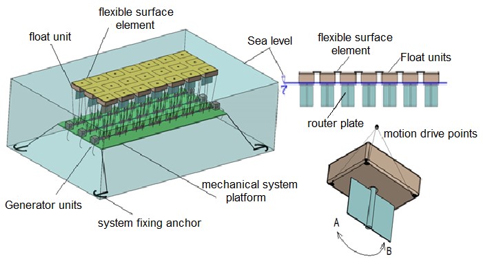
• In this new design, the flexible surface floats slightly above sea level depending on the floats, and the incoming waves are directed under the flexible surface by the buoys carrying the flexible surface.
• Under each float that carries the flexible surface, there are routers that can rotate around its axis (in the direction of A-B) with a wave effect, and which can generate channels under the flexible surface by rotating the routers at the bottom of the entire float.
• The direction of the wave to the system is not important, the wave is directed to the bottom of the flexible surface.
• Each float and the resilient surface have multiple drive points for transmitting the wave effects, so as to create several drive points along the resilient surface, all movements on the flexible surface have been attempted to be transferred to the mechanical loop.
• The in-depth length of the resilient surface is used as a control for the wave effect, the transmission of the wave power to the loop, a controlled power transfer is provided, the in-depth distance in the system is used as a time-saving parameter for us to transfer the wave power.
• The fact that the flexible surfaces and the buoys are not high above the sea level do not form a large resistance surface against the wave, so that if the wave cannot penetrate under the flexible surface at the unpredictable wave heights, it can easily go over the flexible surface without causing much resistance and destructive effect and does not damage the system.
• In this design, the platform carrying power shafts and generator units can be fixed by positioning them below sea level. Since the system is not obliged to use a cage system that is placed on the carrier floor, as it is seen in the figure, it has gained a suitable design for open sea applications.
• The design, which has become suitable for open sea applications, has gained an aesthetic structure visually.
• With this structure of the system, modular production provides easier transportation and assembly advantages.
• With this design, the system has become more suitable for both offshore and offshore applications.
• In the design of this system, only flexible surface elements are seen on the sea surface.
The platform which is in the sea and the mechanical parts is partially floating and is immersed in the desired amount and fixed at the desired sea level by the sailor anchors. The application in this design allows the application of the sea depth at 20 mt or more.
• The platform which is in the sea and carrying the mechanical parts is partially floating and is immersed in the desired amount and is fixed at the desired sea level with the sailor anchors. The application in this design allows the application of sea depth at places 20 mt or more.
• Mechanical system elements inside the sea do not contain any materials causing marine pollution by creating oil and dirt in the marine environment. Some of the system elements are made of stainless material, some of them are composite materials, some of them are synthetic and seawater and they do not harm the environment. Some iron parts are painted with special paints against rust formation and precautions are taken so as not to pollute the sea.
• The power transmission ropes connected to the float and the flexible surface swivel into the one-way pulley and allow the flexible surface movements moving with the wave effect to rotate to obtain energy from the power shaft.
• The buoys under the flexible surface and the flexible surface will cause a movement in the direction of B in the other part of the float while creating an upward movement in the direction A with the wave contact and the first contact of the wave. All wave effects under the flexible surface will cause different movements to be affected across the entire surface and at all surface points, and this interaction will continue in the period of progression of the wave under the entire flexible surface.
• Relative impacts in the A – B directions of the wave underneath the flexible surface previously described and continuing along the entire surface, and all of these movements are transmitted directly to the power shafts with one-way rollers without the need for much process steps with the help of power transmission ropes.
• These relative effects on the flexible surface with the effect of the wave effect, the movement at each flexible surface point affect the other flexible surface point near this point and cause a movement at this point, our attempt to catch all these movements with our many drive points is serious on system efficiency. contributes a contribution.
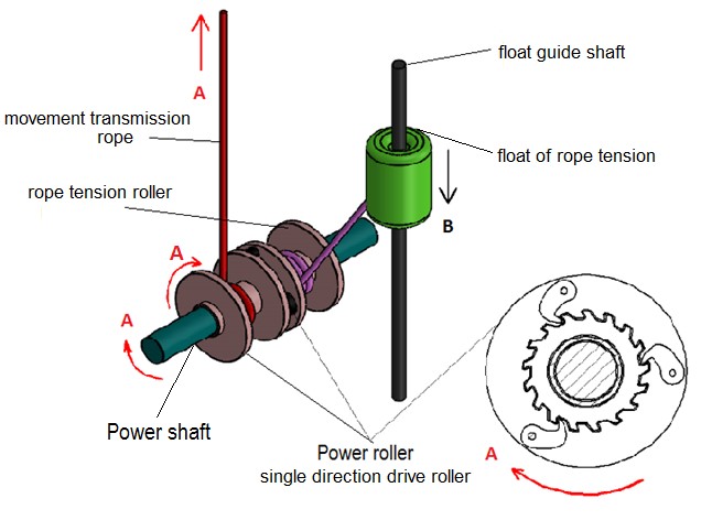
• Only one of the power transmission ropes connected to the float and the flexible surface is seen in the upper figure. The upward movement of the flexible surface with the wave effect will also pull up the power transmission rope connected to it in direction A. This movement of the power transmission rope will turn the unidirectional pulley clockwise in the direction A, and in this one-way pulley it will turn the power shaft clockwise (A) by means of gears which will enable one-way rotation of the power shaft.
• The rope tension roller connected to the unidirectional pulley and rotating with it will rotate in a clockwise direction during the real work period of the power shaft (along the upward movement of the flexible surface) and will pull it downward in the direction of the rope tension buoy B by means of the rope connected thereto. Since the rope tensioner buoy has a volume of swim ability, it will want to move towards the surface of the water continuously and this physical condition will always keep the power transmission rope with a certain tension by means of the rope and the rope tensioner.
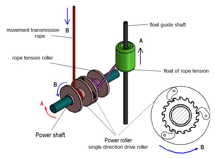
• During the progression of the wave under the flexible surface and the downward period of the flexible surface, the power transmission rope will tend to form a downward gap, so that the rope tensioning pulley and the rope tensioner can be used to ensure that such a gap does not occur and that the flexible surface is stretched to turn the power shaft even at the smallest upward movement. We use the buoy.
• It will move upwards in direction A with the buoyancy of the rope tension buoy in the absence of an upward pulling force on the power transmission rope. This upward movement of the rope tensioner buoy will cause the rope tensioning pulley and thus the unidirectional pulley to be turned into a tensioned state by rotating it counterclockwise in the direction of B by taking the blank of the power transmission rope.
• The toothed system on the one-way spool rotates in idle direction when rotating in the direction of the threaded system B, not forming a resistance, and allowing the unidirectional pulley to rotate in a non-resistive manner, allowing the transmission of the power transmission rope wrapped around it to be wound by means of the rope tension roller. Due to this feature of the unidirectional pulley and gear system, the power transmission rope at this driving point is stretched to produce power at the next effect as described.
• The power transmission rope at each drive point enables the power shaft to rotate clockwise in the direction A and generate electricity by means of wave action and flexible surface movement. The power transmission ropes that do not work effectively and are in vain will turn the power transmission rope to the unidirectional pulley and rotate without any counter-clockwise direction of rotation with the help of the rope tensioner buoy
ADVANTAGEOUS FEATURES OF OUR CYCLE SYSTEM
• The wave is directed under the flexible surface, the direction of the wave does not matter.
• In order to prevent the wave which is directed under the flexible surface to move along the flexible surface and to prevent its escape from the system as much as possible, we use the guides under the flexible surface and move together with the buoys on the main structure. to form channels under the flexible surface)
• We control the progression of the wave under the flexible surface by determining the depth of the system in relation to the wave façade, so as we transfer the power of the wave to shafts, we spread this effect over a period of time and provide a controlled power transfer, we increase the system efficiency.
• We transfer the effects on the flexible surface of the wave which we made under the flexible surface by the drive points we have received from many points (86 drive points in our system, one-way pulley and rope connection). The wave of surviving from any point is prevented from passing through the system by trying to be caught at another point. We aim to transfer the energy acting on the whole surface with the aim of capturing all surface movements (surface absorber), which significantly increases our efficiency in this approach.
• In the system, when the wave does not work in a real sense by the flexible surface, it is moved again without losing anything from its energy and working again with the drive point at another point of the flexible surface.
• Since the flexible surface, we have placed on the sea in our system is sensitive to even the smallest wave movements, it provides advantages for all application areas and contributes positively to efficiency.
• As our wave system is directed under the flexible surface and the flexible surface thickness is very low, the waves that cannot penetrate under the flexible surface can easily move over the flexible surface and can not create a destructive effect on the system.
• Since the wave effect is transmitted directly to the power shafts in the system setup, the lack of process steps because the energy is produced increases the efficiency by reducing energy losses.
• Simple elements of the system elements to provide operational convenience, with less failure percentage provides stable operation
• Simple and easy structure of the system elements provides a great advantage in terms of initial installation costs
• The system can be produced as modular units according to the application area, which provides a wider range of applications while also providing ease of transportation and installation.
• The next stage of our system to get rid of the main cage structure and modular manufacturing will allow for open sea applications and will provide ease of offshore transportation installation (Successful with the first field prototype cycle system we run with the same cycle of the system elements on the surface of the sea was removed from the structural hardware. and it is completely aesthetically pleasing, with an unobtrusive look and, more importantly, suitable for offshore applications.